Page 71 - _ 180314 Special Yucaipa GSA Packet
        P. 71
     Float Valve 4
                  Low-pressure    Pressure
                      sensor      regulator
 OPTIONAL         PS        PR
 Water storage tank                                                          Manifold
 (20,000 gal)                                                                4-inch pipe connection to
                                                                             one 2-inch and two 1-inch flow lines
 Flow
                                                                 Flow meters
                                                                 hand valves
 3-inch fire hose
 Flow meter +                                                         High level switch
 backflow preventer                                                    Lifting eye
 Fire hydrant  and hand valve
                                 3.0’
                                                                      Float Valve 1
                                 2.5’
                                                                      Float Valve 2
                                 2.0’
                                                                      Float Valve 3
                                                                      Low level switch
                                                                       Steel gravity base
                                      30’ x 30’ x 5’ Basin
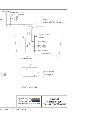
 Notes: Telemetry calls out when ponded water level is less than 1 foot
 Telemetry calls out when ponded water level is greater than 4 foot
                                                      3’
 Process Flow
 1. Fire hydrant with back flow preventer is primary water source  1.5”
 2. Pipeline from hydrant to manifold is 3-inch fire hose (preferred)         Steel gravity base
 3. Optional Water tank outlet could require separate hand valve and flow meter  (top down view)
 4. Manifold to basin tree 4” PVC to three PVC lines (two 2-inch and one 1-inch)  2’  Surface area on  2
 5. Float valve 1 opens at H O < 3.0’ depth                                   ground is 180 in
 2
 6. Float valve 2 opens at H O < 2.5’ depth
 2
 7. Float valve 3 opens at H O < 2.0’ depth
 2
 8. Optional Float valve 4 closes when water tank is full
                                         Basin Tree Detail
 Not to Scale
                                                                                          Figure 3
                                                                                    Infiltration Test
                                                                             Process Flow Diagram
 Yucaipa Groundwater Sustainability Agency - March 14, 2018 - Page 67 of 226
     	
